
How to measure the diameter of a steel wire rope and what is Extension Properties?
How to measure the diameter of a steel wire rope?
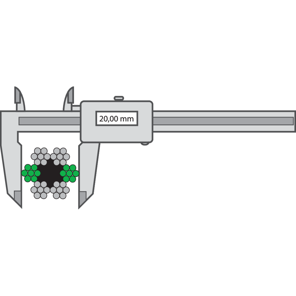
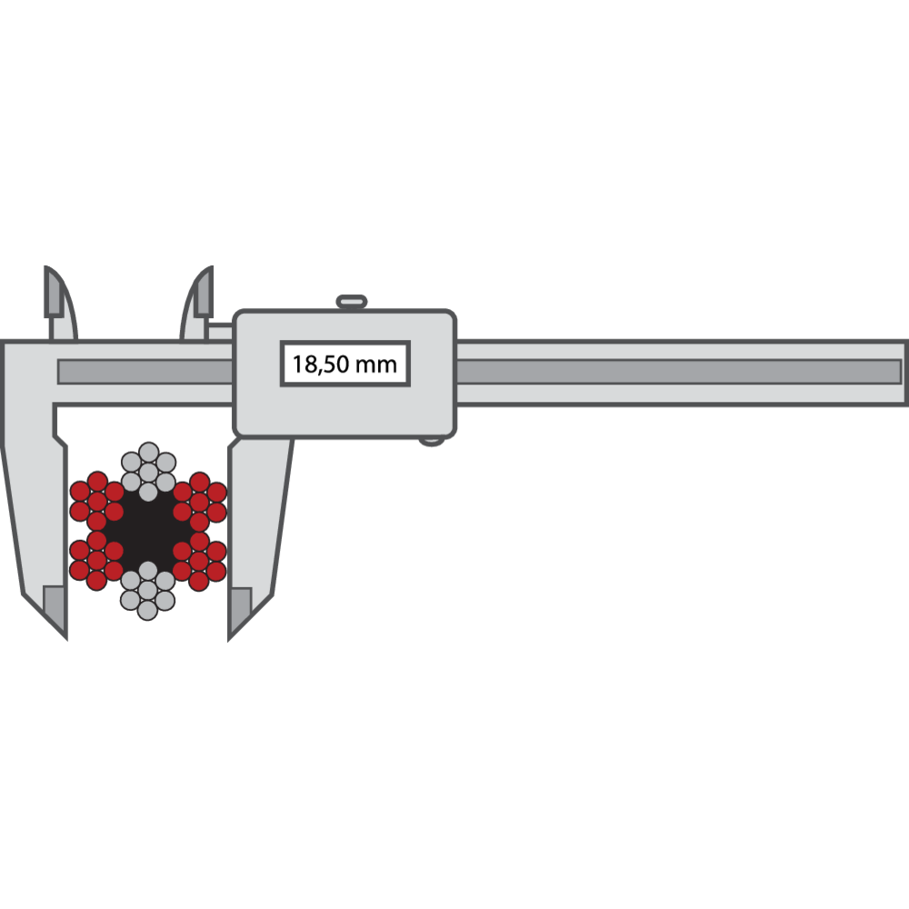
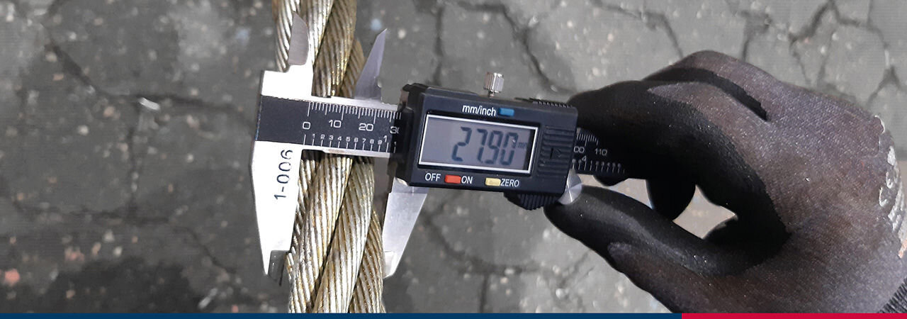
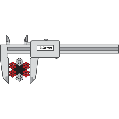
The rope diameter should always be checked before installation. Measure a straight part of the rope. Two parts with minimum distance of one meter should be measured. At every point two measurements should be done, with an angle of 90 degrees displacement in relation to each other. The average between the two measurements should be according to the tolerance detailed in the tables below.
Steel wire ropes for general applications
|
|---|
|
|---|
Steel wire ropes for person elevators
|
Nominal |
Tolerance for nominal diameter for ropes with fibre core/synthetic core | Tolerance for nominal diameter for ropes with steel core | ||||
|---|---|---|---|---|---|---|
| Unloaded | Loaded to 5% of min breaking load | Loaded to 10% of min breaking load | Unloaded | Loaded to 5% of min breaking load | Loaded to 10% of min breaking load | |
| mm | max% | min % | min % | max % | min % | max % |
| ≤10 | +6 | +1 | 0 | +3 | 0 | -1 |
| >10 | +5 | +1 | 0 | +2 | 0 | -1 |
|
|---|


Steel Wire Ropes Extension Properties
Any assembly of wires spun into a helical formation (either as a strand or a wire rope), when subjected to a tensile load, can extend in three separate phases, depending on the magnitude of the applied load:
Phase 1: initial extension
Phase 2: elastic extension
Phase 3: permanent extension (thermal elongation and contraction, rotation, wear and corrosion)
Phase 1 and 2 are very important because they are a normal part of the rope bedding in and working of the rope. Phase 3, on the other hand, can be caused by the wrong choice of rope or lack of rope inspection. The phases occure in sequence in all ropes that are exposed to a gradual increased load. Due to this a new rope, when overloaded, will go through phase 1 and 2 before the third phase (permanent extension) begins.
Phase 1: Initial or permanent extension
This phase of extension of the rope depends on the construction of the rope and can be explained as follows:
When loading a new product, extension is created by the bedding down of the assembled wires with a corresponding reduction in overall diameter. This reduction in diameter creates an excess length of wire which is accommodated by a lengthening of the helical lay.
When sufficientely large bearing areas have been generated on adjacent wires, to withstand the circumferential compressive loads, this mechanically created extension ceases and the extension in phase 2 commences.
The initial extention can not be accurately determined and depends on, apart from the strand or the rope construction, the various loads and the current load frequency.
It is not possible to quote any exact values for various constructions but the following approximate values can be used to give reasonably accurate results.
|
|---|
Phase 2: Elastic extension (elongation)
Following Phase 1, the rope extends in a manner which complies approximately with Hookes Law, i.e. stress is proportional to strain.
The proportionality factor normally is a material constant called Modulus of Elasticity (E-modulus). To steel wire ropes the E-modulus is more of a construction constant than a material constant.
The elastic extension can be calculated as follows (Hookes law):
Elastic extension (mm) = (W x L) / (E x A)
W = applied load (kg)
L = rope length (mm)
E = elastic modulus (kg/mm2)
A = area of rope - circumscribed circle (mm2)
The modulus of elasticity varies with different rope constructions. Due to specific manufacturing factors, wire dimensions and other factors, the E-modulus varies between different wire ropes of the same construction and dimension. If the exact E-modulus value of a certain rope is necessary a specific modulus test needs to be done for that rope.
The elastic extension is valid until the proportionality or elasticity limit is reached. Once the load exceeds this limit , extension according to phase 3 takes place. The elasticity limit is defined as the largest force where the rope returns to its original length when unloaded.
General E-module of the rope construction
|
|---|
These values are valid for ropes operating with a safety factor of 5:1. With lower safety factors the modulus of elasticity indicated are increased and for higher safety factors they reduce.
Phase 3: Permanent extension
The permanent, non-elastic extension of the steel caused by tensile loads exceeding the yield point of the material. If the load exceeds the Limit of Proportionality, the rate of extension will accelerate as the load is increased, until a loading is reached at which continuous extension will commence, causing the wire rope to fracture without any further increase of load.
Thermal Expansion and Contraction
The coefficient of linear expansion (∝) of steel wire rope is 0.0000125 = (12.5 x10⁻⁶) per o C and therefore the change in length of 1 metre of rope produced by a temperature change of t o C would be;
Change in length Δ| = ∝ |o t
where:
∝ = coefficient of linear expansion
|o = original length of rope (m)
t = temperature change (o C)
The change will be an increase in length if the temperature rises and a decrease in length if the temperature falls.
Extension due to Rotation
The elongation caused by a free rope end being allowed to rotate.
Extension due to Wear
The elongation due to inter-wire wear which reduces the cross-sectional area of steel and produces extra constructional extension.
Example:
The total elongation of a 200 m length of steel wire rope type 28 mm 265-wires (6x36-IWRC) at a tension of 10 tonnes (safety factor 5:1) and with an increase in temperature of 20°C.
According to phase 1:
Permanent constructional extension = 0,25% x total rope length = 0,25% x 200 m = 500 mm.
According to phase 2:
Elastic extension = (W x L) / (E x A) = (10000 x 200000) / (6000 x 615,4) = 540 mm.
According to phase 3:
Thermal expansion = 0,0000125 x L x t = 0,0000125 x 200 x 20 = 50 mm.
Total extension = 500 mm + 540 mm + 5+ mm = 1090 mm.


Do you have any questions?
If you have any additional questions, please contact us and we will answer you.
